Two-level Converter
Power electronic converters are key interfacing devices that enable the integration of renewable generation, energy storage, and HVDC links. This section models the interaction between the converter and the surrounding AC/DC network
Generator Model Parameters
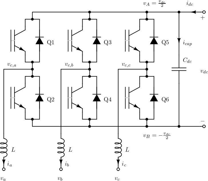
In Figure 1, a two-level converter is depicted. Switches in the same arm are operated complementarily, e.g., \(\text{Q3} = \overline{\text{Q1}}\). In Figure 2 is depicted one arm operation, where is visible that when Q1 is conducting \(v_{c,a} = \frac{v_{dc}}{2}\), and when Q3 conducts \(v_{c,a} = -\frac{v_{dc}}{2}\).
VSC can have square-mode operation, where each switch (IGBT) conducts for a half period, with the phase shift of \(\frac{2\pi}{3}\) for each phase Anaya-Lara et al. (2014). This modulation is no longer used because it cannot vary magnitude.
Therefore, VSCs are usually controlled using Pulse Width Modulation (PWM). PWM can be designed in various ways, but the goal for it is to ensure that the averaged (over the converter’s switching frequency) currents and voltages have the desired waveforms (usually sine waveforms).
PWM modulated two-level VSC should have desired voltage/current waveforms. Therefore, for the further analysis is introduced dimensionless parameter denoted as modulation index and represented as \(m_j\) for \({j \in \{a,b,c\}}\) being the phase. For the each switching interval \(m_j(t) \in [0,1]\).
The converter operates in such manner that in the steady-state is \(v_A = \frac{v_{dc}}{2}\) and \(v_B = -\frac{v_{dc}}{2}\). The following equations can be written
\[\begin{equation} \widehat{v_{C,j}} = \widehat{m_j} \, \frac{v_{dc}}{2}, \end{equation}\]
\[\begin{equation} L\frac{d\widehat{i_j}}{dt} = v_j - \widehat{v_{C,j}}, \end{equation}\]
\[\begin{equation} C_{dc} \frac{d\widehat{v_{dc}}}{dt} = \widehat{i_{cap}}. \end{equation}\]
In addition we can write energy-balance equation as: \[\begin{equation} \widehat{v_{dc}} \, \left(\widehat{i_{dc}} - \widehat{i_{cap}}\right) = \sum\limits_{j \in \{a,b,c\}} \widehat{v_{C,j}} \, \widehat{i_j}, \end{equation}\] which gives a connection: \[\begin{equation} \widehat{i_{cap}} = \widehat{i_{dc}} - \frac{1}{2} \, \sum\limits_{j \in \{a,b,c\}} \widehat{m_j} \, \widehat{i_j} . \end{equation}\] Finally, the complete set of differential equations with neglected variations on DC voltage is
\[\begin{equation} \label{eq:11} v_{C,j} = m_j \, \frac{v_{dc}}{2} \end{equation}\]
\[\begin{equation} \label{eq:22} L \frac{d i_j}{dt} = v_j - v_{C,j} \end{equation}\]
Averaged notation is not used in the previous equations (\(\ref{eq:11}\)) and (\(\ref{eq:22}\)) to simplicity of description.
A two-level converter is not created as a new component, but it is integrated inside different RES, usually in a back-to-back configuration.
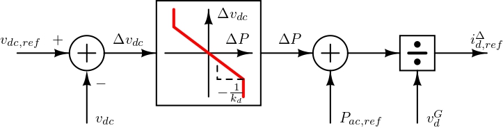
All VSCs (two-level and MMC) will be described using the dc and dq-frame coupling admittance components. Their admittance is the size \(3 \times 3\), and the relationships are: \[\begin{equation} \begin{bmatrix} i^\Delta_d \\ i^\Delta_q \\ i_{dc} \end{bmatrix} = \begin{bmatrix} Y_{dq}(s) & a_{2 \times 1}(s) \\ b_{1 \times 2}(s) & Y_{dc} \end{bmatrix} \, \begin{bmatrix} v_d \\ v_q \\ v_{dc} \end{bmatrix}, \end{equation}\] or equivalently with the standard direction of \(i_{dc}\) entering the converter and \(i^\Delta_{d,q}\) exiting the converter.
These equations are used for modelling the VSCs connections, both for the back-to-back VSC connection, which is applied for wind turbines, hydrogen, and PV systems, but also from VSCs (MMCs) used for the interfacing of DC and AC sides.
Code Explanation
For detailed code information, see the Harmony manual.